| Author |
 Replies: 18 / Views: 3,280 Replies: 18 / Views: 3,280 |
Page 2 of 2
|
|
|
|
Pillar of the Community
United States
1427 Posts |
|
|
Pillar of the Community
United States
1359 Posts |
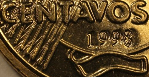
Nice bottom pic. That looks familiar. On incused devices, its like the field of Lincoln Cents. Trying to figure out how to explain it it.  When the date is doubled like on a Lincoln DDO. The date is wider or bigger because the field is the incused area. The incused part is still the high point on the die like the field on Lincolns. Incused letters would get smaller on a doubled die because the design around it is whats actually doubled. Not the letters because that more-less is the field of the coin. Edited by Kloccwork419
02/04/2021 10:20 am
|
|
Pillar of the Community
United States
4424 Posts |
Quote:
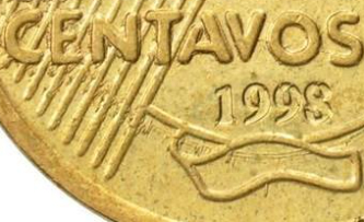
how they came to the conclusion that incuse devices would be thinner/smaller if hub doubling is present so that I can be on the same page. Well, they simply found examples. The incuse date on the Brazilian Centavos pictured above are good examples. So are the major US shield cent doubled die reverses with the incuse E PLUIRBUS UNUM. On both examples, the incuse lettering has decreased in size. I tried quickly making a visual of the process but I don't think it's that great. 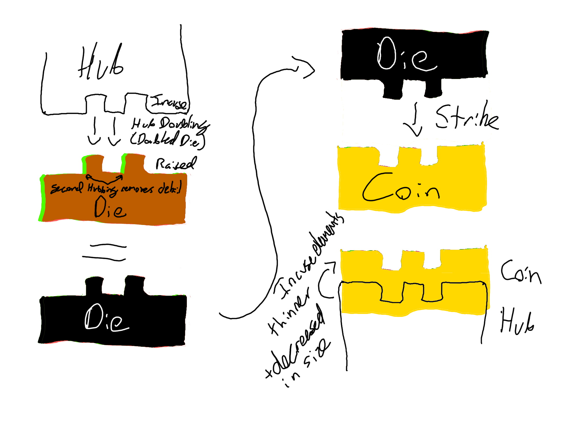 The second hubbing removes the raised detail on the die, which, in turn, become the incuse detail on the coin. Also, I'm curious to see what you did with your CAD software. Seeing that may help us clearly understand what you're think and where you're at. Edited by Tanman2001
02/04/2021 11:36 am
|
|
Pillar of the Community
United States
3003 Posts |
here is what I think happens i am GUESSING there is more then one strike to make a die die gets hit the first time. if the hub (or die?) shifts between the first and second strike, the hub smashes down on part of the raised area on the die. i GUESS I should read up on how they make hubs and dies... stick figure representation: 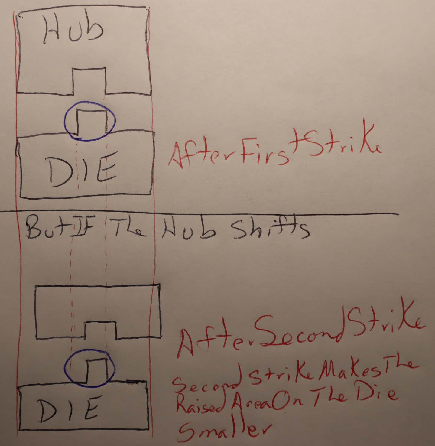 |
|
Pillar of the Community
United States
1427 Posts |
|
|
Pillar of the Community
United States
1667 Posts |
I just blame it on the coin gnomes and call it a day.
|
|
Bedrock of the Community
United States
10635 Posts |
Very interesting!  |
|
Pillar of the Community
 Canada
1189 Posts |
Sorry for the delayed response, I spent most of my day in the ER getting a broken nose realigned and couldn't use my computer. Quote:
Also, I'm curious to see what you did with your CAD software. Seeing that may help us clearly understand what you're think and where you're at. Tanman2001, Here you go, fair warning though, this coin I designed when I was daydreaming about what it would be like if Canada still made pennies, it is a crude example that I dident get around to finishing but it serves its purpose for what I use it for. 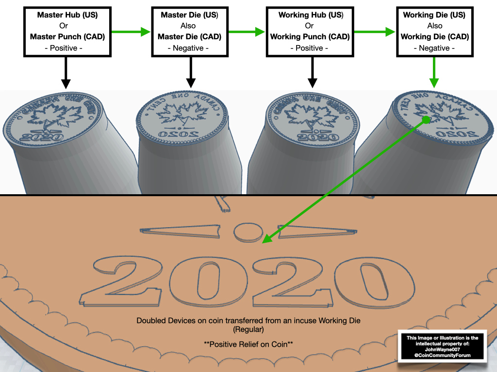 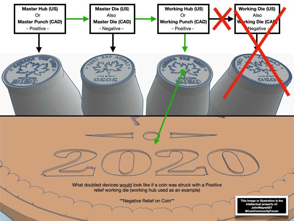 Notice how the "thickness" didn't change at all regardless of devices being raised or incuse. I can manipulate the dies shown in the pictures to be doubled by even the smallest degree in any direction, height, or angle while using what I call "animated hubbing" which is virtually identical to the actual hubbing process just on a computer instead of steel and presses. As I said, I am a hands-on learner, and also very thorough. PS. the working hub used as an example is obviously supposed to be mirrored (date backwards on the working hub) but for this purpose, I didn't bother to mirror it as I'm sure most already knew that. Finding and discovering modern Canadian doubled die varieties since 2018. 2023 Recent Publications: Modern Canadian Doubled Die Varieties - First Edition PDF & Paperback https://www.mcddv.ca - (New Site, Second Edition, Registry & Services coming fall 2026) Edited by JohnWayne007
02/05/2021 01:10 am
|
|
Pillar of the Community
United States
1427 Posts |
No, the working hub is not mirrored, and I am not sure how you got the doubling on the 1st die, but the hubbing would cut at the devices like Machine Doubling because the way that Incuse devices double is the same way Machine Doubling does. |
|
Bedrock of the Community
United States
62064 Posts |
The example is flawed because the hub doubling is not on the Master hub, it is normal. These are doubled dies. These are created on the working die from the working of the working hubs misalignment during the die creation. The example I'm showing is on the single squeeze process. The first kiss before the hub pressure makes a mark on the inside devices, then full pressure adjusts the position. Thus the center areas are affected, but the rest of the devices, are cancelled out by the hub. Thus the Bar cents were the first examples of this. A spread on the raised devices.  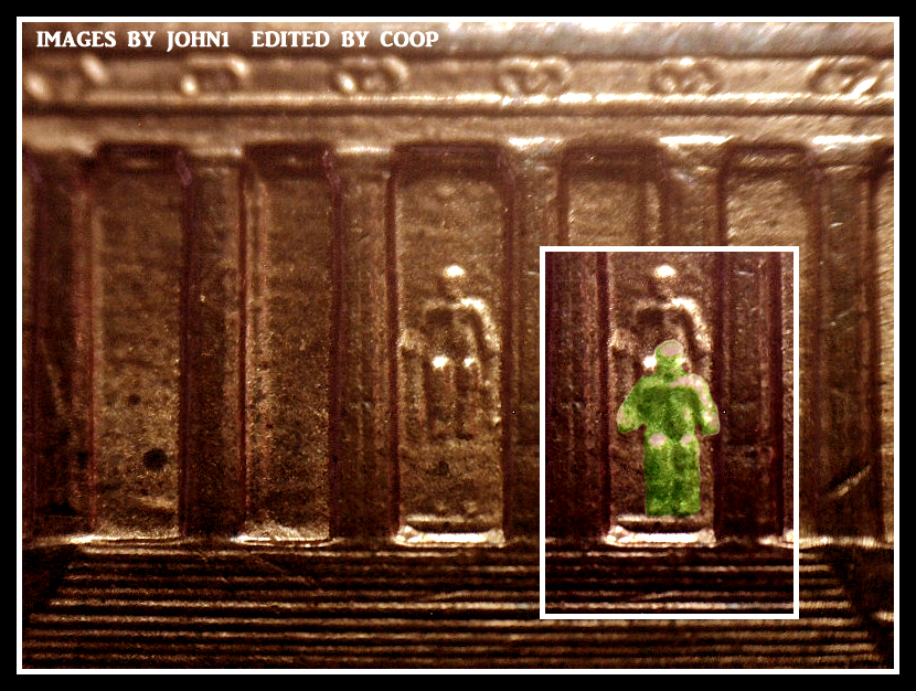  Thus when the rotation was incorrect, it moves during the full pressure. (rotated statue) 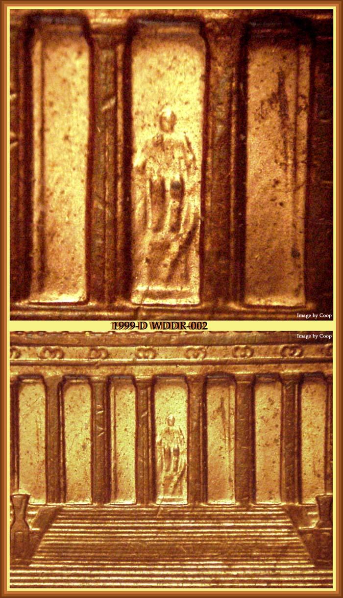 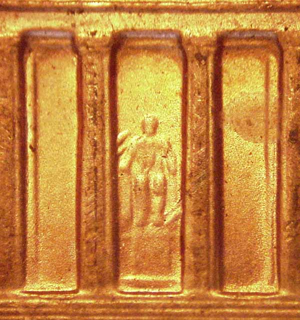 Note how just a certain area is affected on these raised devices. http://varietyvista.com/01e%20LC%20...3PDDR001.htmNote on this die we see both raised and incuse devices affected on the DDR? Raised devices enlarged, incuse devices reduced in size. Same on all other DDR's that are raised. The central area is affected: )).jpg) 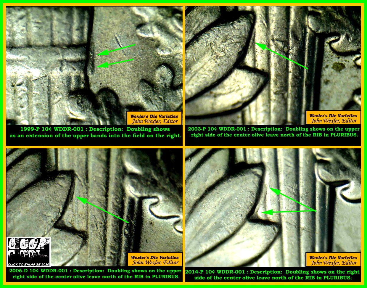 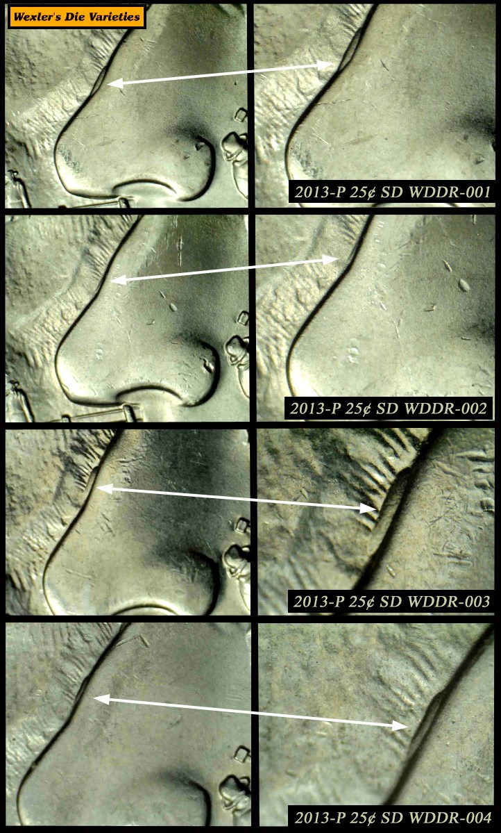 Incuse devices formed differently on the doubled dies:   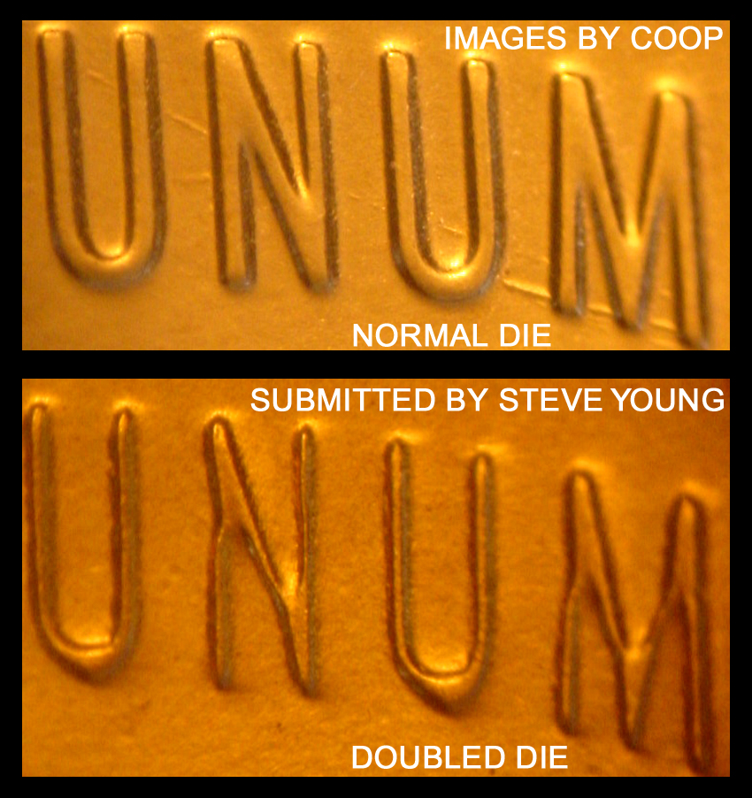 Why this happens, I wonder it the movement of the hub after the moving into the correct location affects these. But it happens on several years, but not always. I feel it might be the angle the kiss happens, that creates this: http://varietyvista.com/01e%20LC%20...5PDDR001.htmThis one, has just one image, but you can see that is is showing reduction from the image we see. But this one is stronger. On incuse devices, we see Machine Doubling enlarging the devices on the same areas:   This is my explanation as I can figure out. Hub doubling creates doubled dies on both incuse and raised devices. But not always the same way. Thus the differences in doubled dies. |
|
Pillar of the Community
Canada
1189 Posts |
This is exactly what I am talking about, you guys are so focused on being right that you completely misread and misunderstood what I was saying 100%.
not once did I even mention that that doubling was on the master hub.
What I said, was for this example I am using a working hub as a Working Die (because the devices are raised on a working hub which means it would create incuse devices on a coin).
It literally says right on the photos "Doubled Devices on coin transferred from an incuse Working Die
(Regular)"
Then on the second photo, it says "What doubled devices would look like if a coin was struck with a Positive relief Working Die (working hub used as an example)"
So instead of me taking even more time to create a completely new die sequence just to end up with a raised Working Die that would create incuse devices on a coin just to show you guys, I simply cut out the "Working Die" (red X's) and used the Working Hub to show you guys what would happen when a Raised die strikes a coin.
It is really not that hard to comprehend and I thought you guys would understand without an issue...
As for "mirroring" to further explain, if you have a Master Hub, the date will read the correct way, once the Master Hub is used to create the Master Die, the date and letters on that master die will be backwards. Once the Master Die (backwards letters and date) are hubbed to make the Working Hub it is once again in the correct orientation and will read correctly and not be backwards (mirrored) anymore.
In order to get a date to read the correct way on incuse devices, the devices on the Working Die must be Mirrored backwards OR the coin being struck will read backwards.
It's really not rocket science, it is also not as complicated as everyone makes it out to be, it's simple.
The doubling in the first photo was "doubled" by using a raised Working Die that was doubled.
The second photo was "doubled" by using an incuse Working Die that was doubled.
Finding and discovering modern Canadian doubled die varieties since 2018. 2023 Recent Publications: Modern Canadian Doubled Die Varieties - First Edition PDF & Paperback https://www.mcddv.ca - (New Site, Second Edition, Registry & Services coming fall 2026) Edited by JohnWayne007
02/05/2021 12:01 pm
|
|
Pillar of the Community
United States
4424 Posts |
Quote:
The doubling in the first photo was "doubled" by using a raised Working Die that was doubled.
The second photo was "doubled" by using an incuse Working Die that was doubled. Doubling using a RAISED element would look fundamentally different from doubling using an INCUSE element. What it seems like you did in your images is just duplicate the elements on the hubs and dies instead of replicating the hubbing process of transferring elements from the hub to die. Let's imagine a hub with a large incuse circle directly in the center. That hub is used to create a die. After the first hubbing, the die now has a large raised circle directly in the center, all of the metal around it was pushed down by the hub to create it. Now if a second hubbing is misaligned, a portion of one side of the raised circle will be pushed down, effectively deleting a crescent shape out of the side of the raised circle. The area on the opposite side is unaffected as the second hubbing would not raise any metal pushed down by the first hubbing. So the second hubbing just removed a crescent shaped piece of the circle, the circle is now thinner and has decreased in size. |
|
Pillar of the Community
United States
1427 Posts |
|
|
Pillar of the Community
United States
591 Posts |
Apologies if this is duplicative of earlier explanations, but I thought I'd take a shot at explaining it:
When the coin has incuse devices, the working die that makes the coin has to have raised devices to create the finished effect.
When the working die gets doubled, the raised devices are in effect reduced in size slightly because the second impression or movement (depending on which method is used) is slightly misaligned with the raised device. Because of the misalignment, the metal forming the raised device is depressed, sometimes a little and sometime a lot.
The doubled die is now used to make a new coin, but because the raised devices are smaller on the die, the incuse devices will also be smaller on the coin.
Further, if the doubling/depression of the raised devices is minor and doesn't flatten the affected portion of the raised device all the way to be flush with the fields, you'll end up with a raised device that looks like it has a step or shelf in it.
This raised device will then make an incuse device that also looks like it has a step or shelf on it, which is typically how we describe MD in a coin.
However, since it's an incuse device, it's actually indicative of a doubled die.
Seems counter intuitive at first, I know.
Another way to think about it is like this - If the working hub and die were so misaligned such that the raised device on the die were 90% covered by a non raised area of the hub, what would happen to the raised device? 90% of it would disappear, right?
If this die were then used to make a coin, would the 90% flattened device on the die make a bigger or a smaller incuse device on the coin?
Clearly, a smaller raised die device makes a smaller incuse coin device. Hence doubling on an incuse device can be determined by looking for devices that are smaller in size.
|
|
Pillar of the Community
2226 Posts |
Thanks to all, great topic, discussion and efforts to explain and teach. It sure takes me a couple of slow readings to attempt to comprehend what's being explained and shown.  .  |
|
Page 2 of 2
|
Replies: 18 / Views: 3,280 |
Page 2 of 2
|








 First Page


 Posted 02/04/2021 10:17 am


