I know that I said I would stop posting on this issue but the overlap lengths has really been bothering me. So I would like to advance a new theory about the way this edge may have been applied. It is a new method, I have not considered before but which fits the facts better than the other alternatives I have before me. It also points to a more astute group of forgers than previously believed.
Lets start with the picture from Filip that shows the second join in the edge of the coin - the really clear one which places a circle next to a circle. Here is the picture he posted.
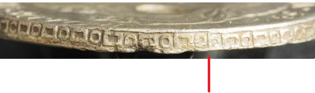
In this picture shows the JOIN location with NO lap. This occurs where there are two circles one following the other, The point is indicated by the red line. I see no trace of the next element presumably a rectangle anywhere. That is precisely what bothered me because I have not seen one exactly like this before.
My previous alternatives for edger machines were - linear consisting of one or two dies and rotary consisting of one (possibly two dies. The dies in these cases were presumed to be made in a fashion that the design progressed in a circle then rectangle pattern along the entire length or circumference. The overlaps occurred where a portion of the edge of the planchet (blank) encountered a die twice.
This edge makes me wonder if a one die edger could simply have used a design with a false join or overlap at the half way point. It would imply that the forgers knew there were two overlaps on the edge.
But I need to get back to the picture and the evidence before I theorize further.
I should start by letting everyone know this is how I normally analyze an edge - using photographs. In this case I took all of Filip's pictures and linked the photos together by segment count. For my convenience, I have always counted edges in pairs of elements - One circle and one rectangle being a unit (a segment). I also position the edge design on the face of the coin (usually the portrait side so that in one file I have both faces of the coin and the entire edge of the coin all in one place with the overlap positions of the edge shown.
I had a slight difficulty positioning the location of this join in relation to the face of the coin (due to foreshortening of the obverse and the location of the join which is along the truncation of the bust between the C in Carolus and the 1 of the date.) - so I decided that if I alter the aspect ratio of the photograph by a vertical factor of 2.5 to 1 versus horizontal I could see the "vertical" components of the edge more clearly as well as getting a much better view of the face of the coin itself.
This is a convenient way to view the edge for me and I do this all the time. But I realize that this may be new territory to people who do not have my background in engineering analysis. So I will describe (mostly with pictures) the way I look at edges.
In engineering design, we were taught to not limit our analysis technique to a 1:1 aspect world. Things that are not visible at 1:1 become OBVIOUS in some cases when one axis is changed in relation to the other. I first learned the technique in roadway design and topography in Geology but it applies in many fields of Civil and structural engineering specifically in strength of materials situations.
Here is the same picture that Filip sent but with the aspect ratio altered - it is the way I would normally view an edge only in this case smaller. This is great on a screen about 42 inches wide blown up as far as pixel count allows.
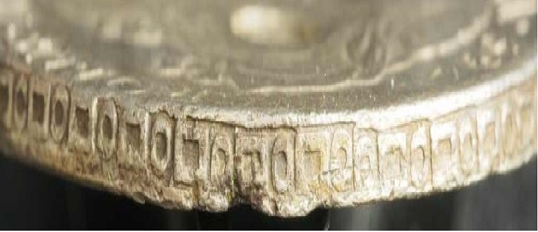
If you notice - this alteration of the aspect ratio allows you to pick out the outlines of EACH individual punch that was used to create the edge die. The place to view the effect best is along the upper edge of each punch where the edge design meets the border. This is also the least distorted area of the photograph nearest the physical center.
Viewed in this manner the sequence of punch application and the alignment segment to segment is readily apparent. At the 1:1 scale it was masked by the predominantly horizontal aspect of the picture. This "distorted" view is a far better view of the actual vertical displacement of the row segment to segment.
A pattern becomes readily visible. The edge design die was created by a die that was punched two elements at a time. Each pair of elements consisting of one circle and one rectangle are aligned with respect to the (segment) pair but they are NOT aligned with respect to the adjacent pairs on either side.
The flat bar edger mill used by Mexico City was a simple but ingenious piece of equipment. The die that created the edge detail was cut at the bottom of a channel - a straight grove in the die metal that was the width of the punch used to make the die. The implications are enormous. The punch placed in the channel could move side to side ONLY as far as the tolerance in cutting the channel allowed. Placing the die design in a channel meant that the coin blank could not pop-out of the edging machine half edged. The blank went in one side where the channel was tapered to allow the edge dies to bite fully - then it rolled along until 1/2 revolution was completed and the fully edged planchet with 2 identical overlaps 180 degrees apart was done. A reversed taper at this end allowed the finished planchet to fall out of the die and a new blank could be inserted for the re turn trip. Simple and labor saving.
To explain my thought process better I put numbers on the following picture at critical places on the photograph. Normally I would dispense with the numbers and use tic marks but I am familiar with how this works and the readers are not.
So in the next picture I mark the ends or joins between each successive punch element pair that was added to the die. The overlaps between the punch segments indicated by cut outs in the adjacent elements can be used to establish the direction in which the die was punched.
Here is the picture.
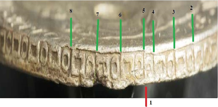
1. This is the join which I believe is a DIE FEATURE cut into the edge die and not an actual overlap where the two dies meet at the end of the run.
2-3. Is one segment that was applied at one time - the top border from 2-3 is straight and does not match the segment before or after,
3-4. Marks another segment it appears that 3-4 was placed before 2-3.
4-5. Is a single element punch that appears to be isolated.
Notice that the segment to the left of line 5 is set deeper. This appearance is repeated elsewhere.
So to try to prove that the join is an intentional die feature I focused in on that small section.
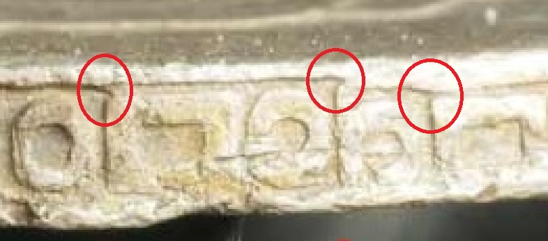
Notice that the segment punch has a projection like a tiny hook at the corner. See three circled in red.
This proves to me anyway that there never was a rectangle to the left of the isolated circle at 4-5.
So based on this - I have another potential type of edger one that uses ONE die with a fake join in it.
All I need now is more data on a bunch more edges analyzed like this - proof follows.