In another thread rmpsrmps stated he rotates the camera on the bellows so as to ensure good coin composition. Until his post today I had accepted that my Minolta tilt shift bellows were only ever going to allow me portrait or landscape orientation of the camera. I have two Minolta Auto bellows III which are both Tilt shift and a non tilt shift Auto bellows IV which I use for parts. rmpsrmps mentioned some bellows are very easy to modify. So I had a look at the parts bellows and discovered the two versions of the Minolta bellows ( common design elements) are extremely easy to modify and that the modification is reversible.
so heres how to do it:
Tools I used fine electricians screw driver set and my calipers for measurign the diametre of coins. Here is the Auto bellows III:
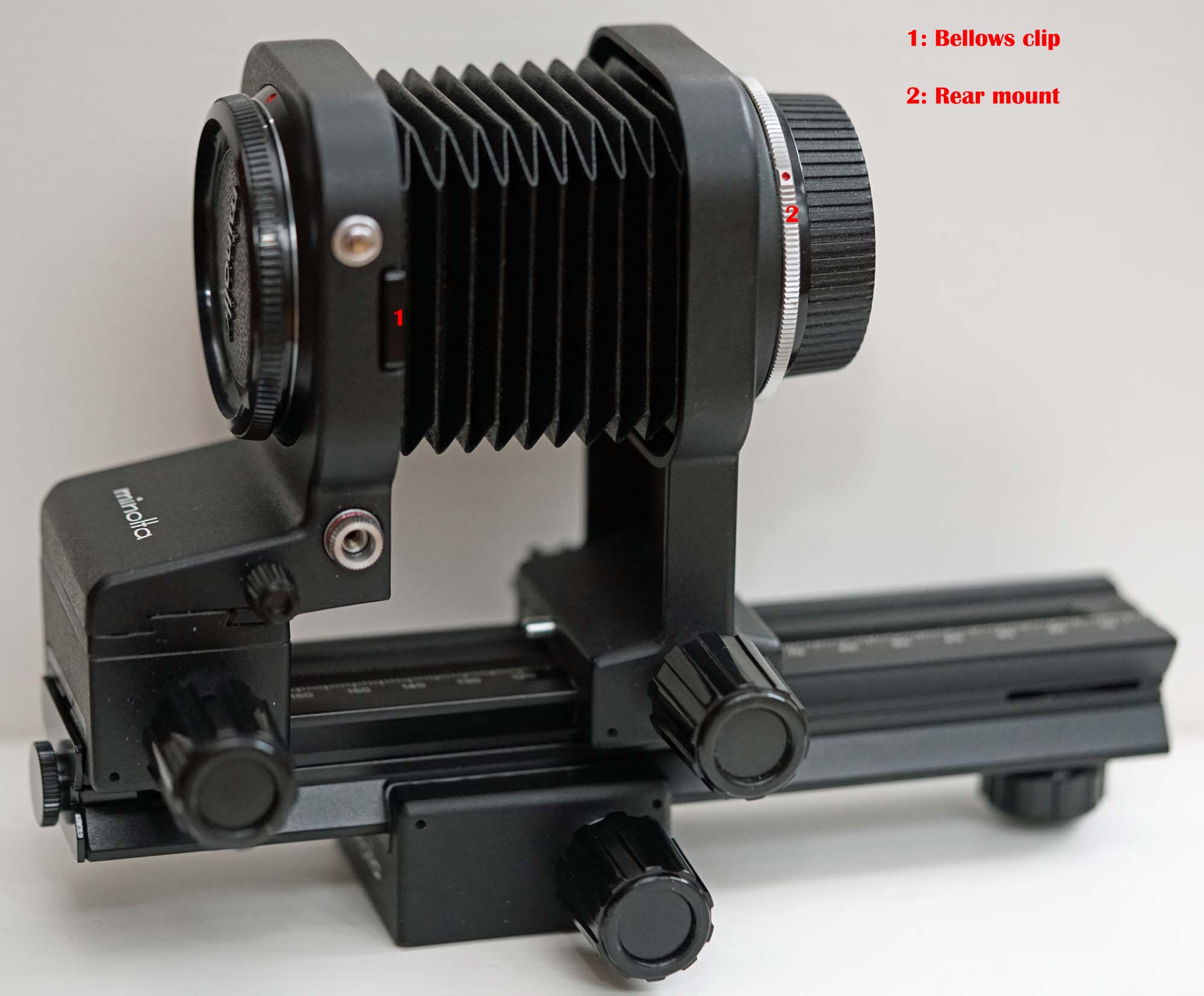
the only difference between this bellows and the IV is that this one is tilt shift. to disassemble the bellows I had to remove the focusing rail and un clip the bellows from the front standard. There are two clips on either side ( the visible one in the picture above is labelled 1. these bellows are designed so that mounted lenses can be reversed with out a reversing ring. For the tilt shift version you un clip the bellows and rotate the front mount (with lens in place) 180 degrees the clipped bellows is designed to clip into the , then standard 55mm diameter filter ring on the front of the lens. For other diameters I use stepping rings. The non tilt shift Auto-bellows IV has the same facility but you have to take the front standard off the rail and mount it reversed. Now the dis-assembly of the bellows is aimed at getting to the mount which is labelled 2 in the picture above.
The first step is to unclip the bellows as shown below:
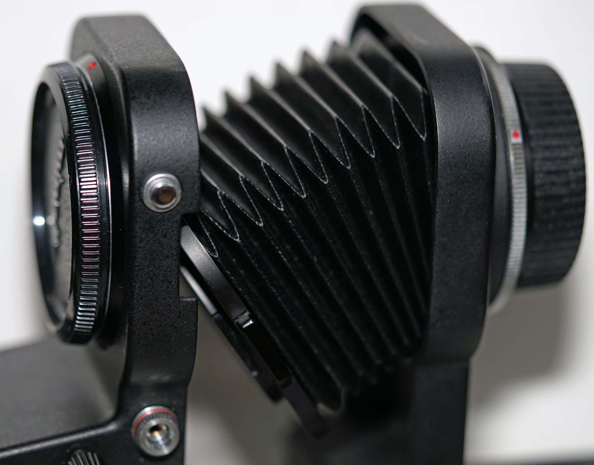
Its then a simple matter to remove the front and rear standards from the bellows rail; Here is the rear standard on its own with the bellows attached:

The locking screw labelled 3 in the above picture can be removed now. that screw locks the camera mount in place and it is even more important when you have the full 360 degrees of movement( don't loose it!).The rear camera mount is labelled 4.
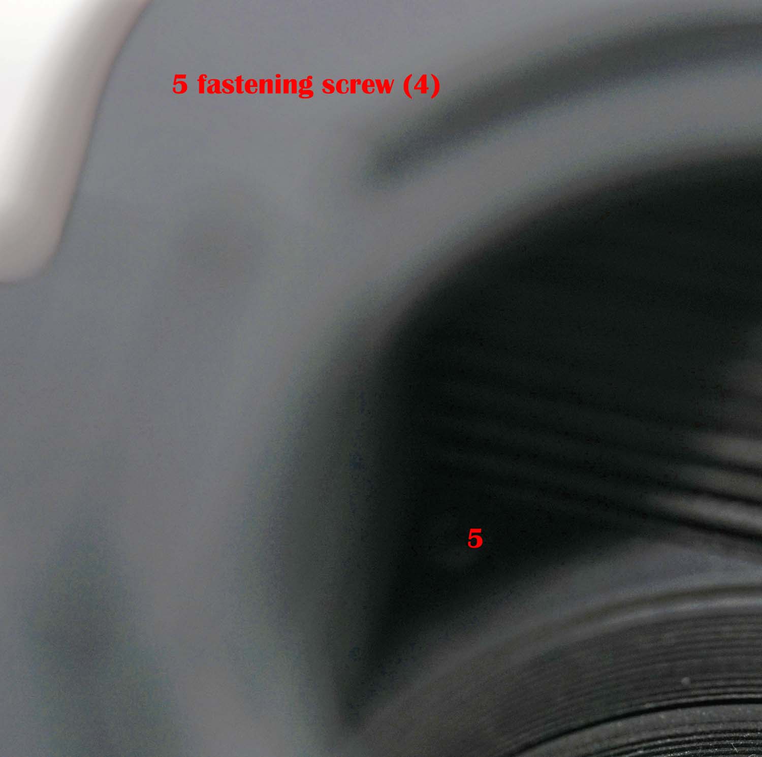
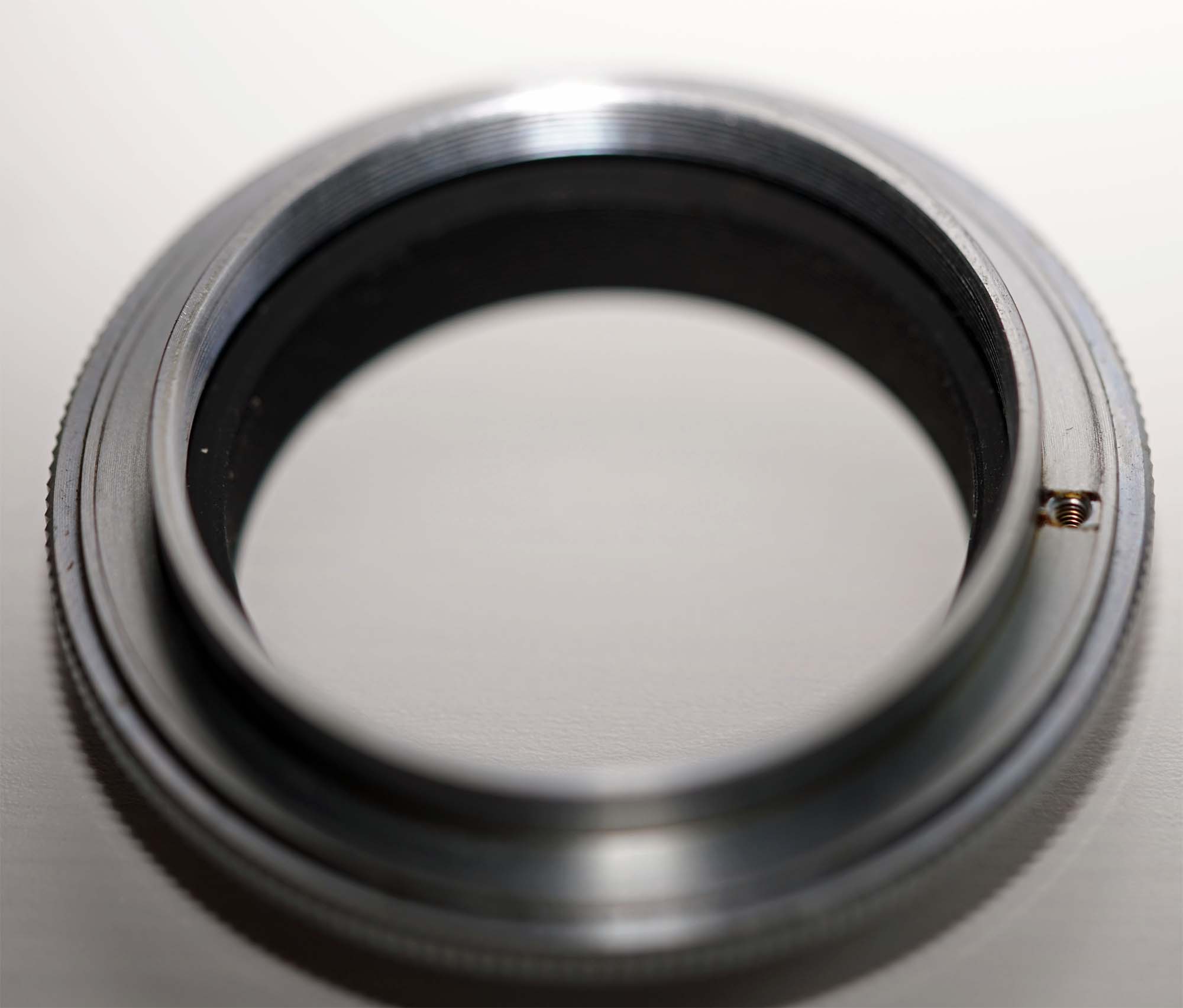
To release the rear camera mount you have to access a locking ring that is hidden by the bellows. there are four tiny screws that need to be removed....I did this over a white tray so if I dropped them I could find them easily: the following photo is not good but it shows the location of one of the bellows attachment screws:
Here is a picture of the rear standard with the bellows detached ( the locking ring is clearly visible):
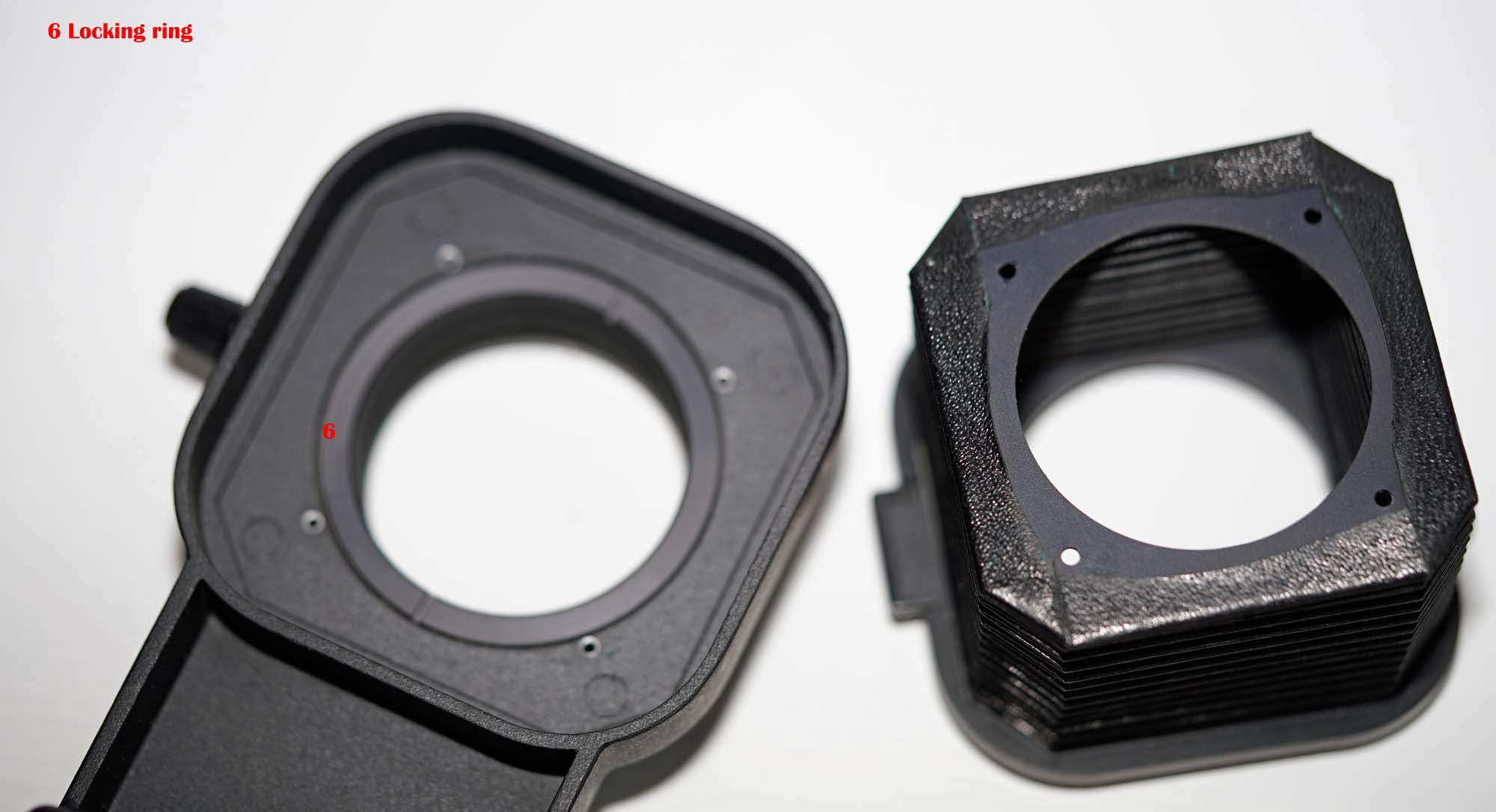
I didn't have a tool to unscrew the locking ring so I reverted to a tried and proved method my calipers:
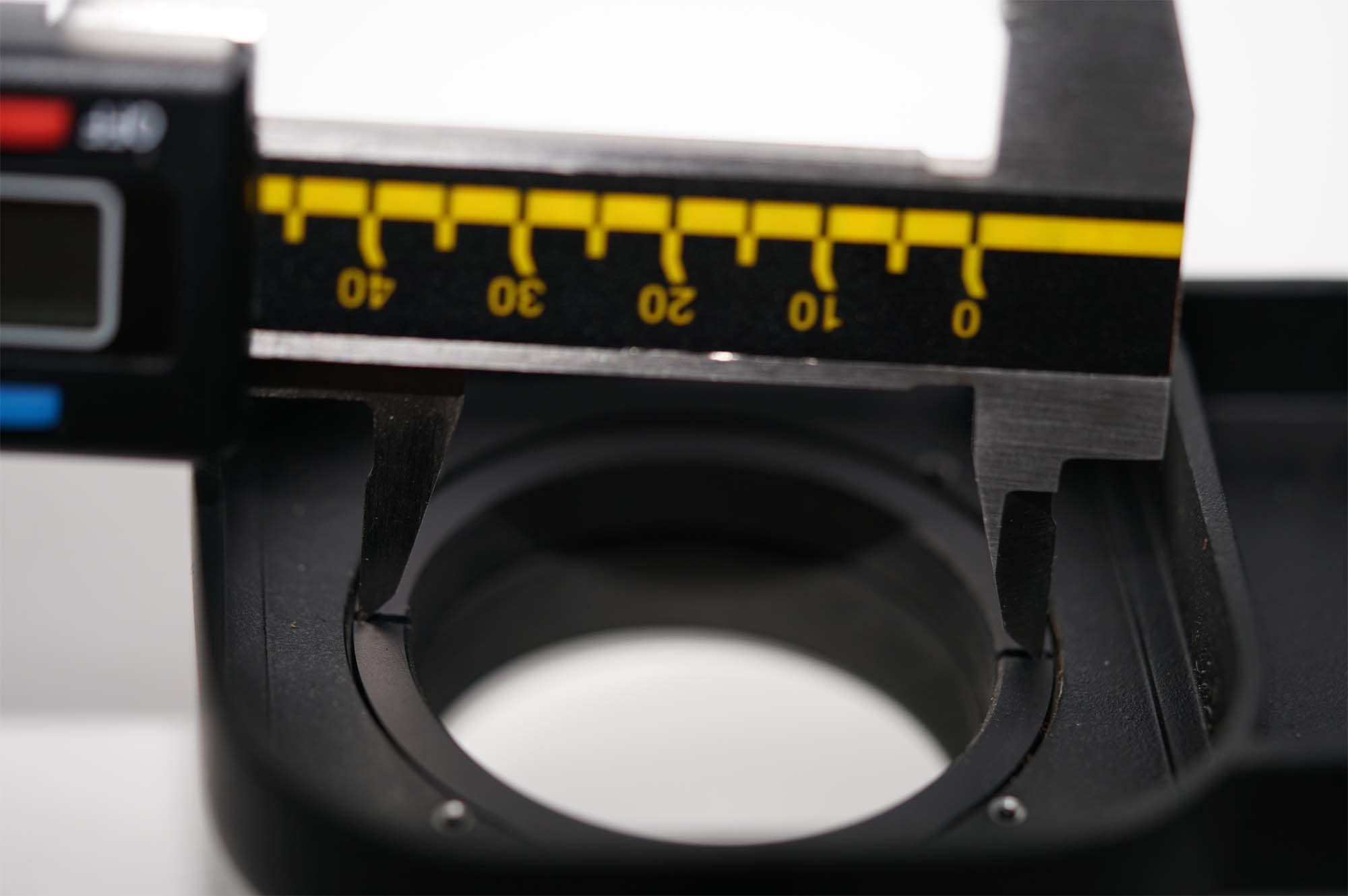
the locking ring was very easy to undo Here is the rear mount disassembled ( It should be obvious what comes next)
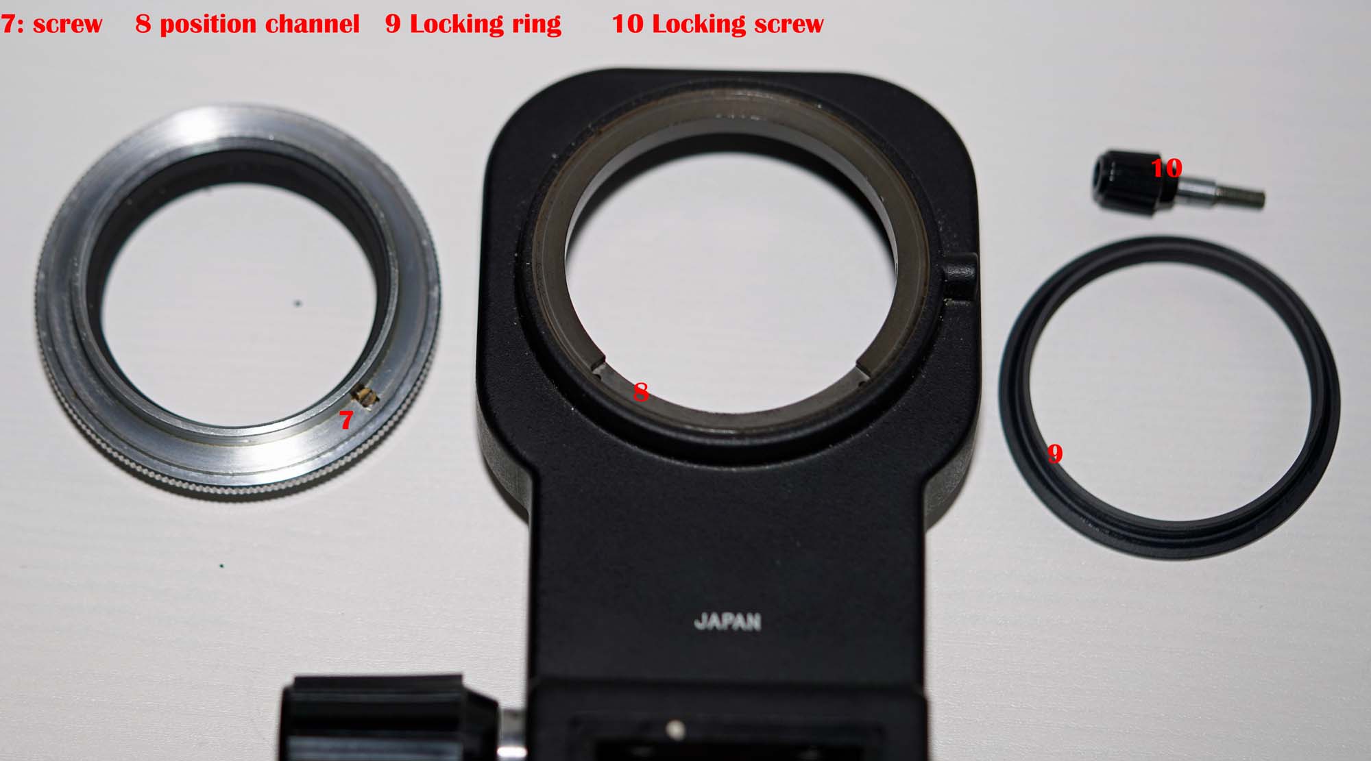
The screw labelled "7" in the above picture engages with the channel labelled "8" this is all that stops the mount from rotating 360 Degrees. The rest is easy:
reassembly was just the reverse process. My biggest problem is finding a place to store the removed screw without forgetting what it is for. the whole conversion took just under 10 minutes