This article is in its raw, unedited form. Please read it and tell me of any edits I need to make to make this more reader-friendly and a better candidate to be sent off to be potentially published in
The Numismatist.
Mathematical Model of the Order of Colors on Toned CoinsBackground Information: Toned coins and the process of toning are highly important to numismatics. Beautifully-toned coins often bring a premium when sold as they are often regarded much more attractive than those that are untoned. As a result, many unscrupulous individuals often use chemicals other than sulfur to fraudulently tone coins in hopes that they will produce a rainbow of colors and also fetch a premium. My exploration will attempt to find a natural order to the colors that appear on coins, specifically silver ones, since most examples of rainbow-toning seem wild and random. Thus, anything that does not comply to that order can be assumed to be fraudulent. I can apply this exploration to detecting these fraudulently-toned coins. To do the application, I will have two coins, pictured here:
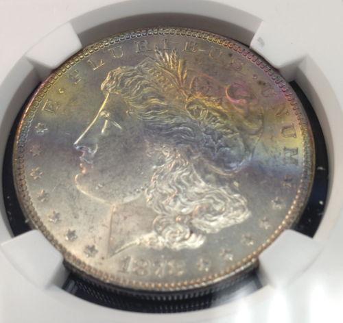
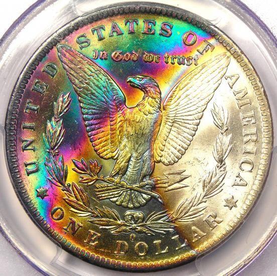
One has original toning and the other has fake toning, and at the end of the exploration, I will use my system in order to prove which is which after analyzing the order of the colors present.
In order to do this successfully, I will have to construct a mathematical model that will successfully predict the order of colors on a toned coin. However, before I do that, I will have to explain key elements of this model.
The Physics: Thin film interference is a phenomenon in physics in which light is distorted through being transmitted to a surface covered in a thin film. Here is a diagram, which I borrowed from the University of British Colombia's website and edited for the purposes of this exploration, showing how thin film interference works:
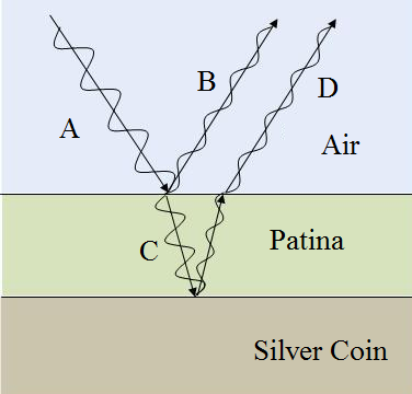
The original light beam (A) is transmitted to a surface covered in a thin film, which in this case is patina. Some of the light beams are reflected off the film (B), but some are transmitted through the film (C) and then are reflected off of the surface underneath the film (D), which in this case is the coin itself, causing these beams to travel a longer distance (University of British Columbia - Faculty of Science). As displayed by this diagram, the amplitude of the original light beam (A) is divided evenly between the two reflected light beams (B and D) (University of British Columbia - Faculty of Science).
When this happens, the light beam is said to have been "shifted" the extra distance traveled inside the thin film. Shifts of 180 degrees, or half of the wavelength of the light beam, cause the shifted light beam (D) to subtract completely from the reflected light beam (B), thus resulting in an amplitude of zero, a phenomenon known as destructive interference. Likewise, shifts of 360°, or a full wavelength of the original light beam, cause the shifted light beam (D) to add fully to the reflected light beam (B), thus resulting in an amplitude equal to that of the original beam (A), a phenomenon known as constructive interference (Russel). These characteristics repeat every period, so a shift of 540°, or 360° more than 180°, will result in a full cancellation of a wave, and a shift of 720°, or 360° more than 360°, would result in a full re-intensifying of the wave. Any other shifts would result in varying intensities in between zero and the amplitude of the original wave (Russel). Here is a diagram created by Media College to give a visual example of what I am talking about:
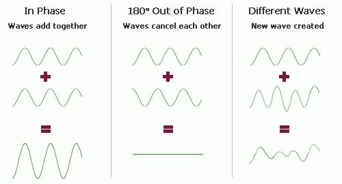
The light color wheel is much different than the pigment color wheel in that the primary colors are blue, green, and red. The secondary colors are cyan, a mixture of blue and green, magenta, a mixture of blue and red, and yellow, a mixture of green and red. However, since the intensities of the reflected colors of blue, green, and red will vary from each other, white light, a primary color of light, and a secondary color of light will be reflected, thus producing a variety of tertiary colors that are seen on a coin's surface (Wikipedia).
Parameters: My model will also make a few assumptions. The most important assumption is that the cone receptors in the human retina respond most strongly to certain wavelengths of blue, green, and red light: 445nm, 535nm, and 575nm, respectively. These values are highly debated, with no "true" number existing. These numbers are round averages of these debated values (Kurz). Another assumption is that the angle of incidence, or the angle at which light is transmitted to the coin's surface, is 90°. I chose this value as it would make the model much easier to make and manipulate, and the extra distance traveled, or the phase shift, would be just twice the depth of the layer of patina. An additional assumption is that the amplitude of the original light beam is 1. I chose this value because any of the values calculated will be out of 1, in effect being percentages, which are easier to deal with and present. Since all of the calculations would be proportional to each other with differing amplitudes, an exact value for the amplitude is not necessary. The last assumption is that the light source produces pure white light, or light that produces equal amounts of blue, green, and red light waves. Such an assumption would make it much easier to formulate a model, even though most light sources do not produce pure white light.
Making the Model:I had to create a model that incorporates the wavelength of the light, the angle of incidence, the depth of the patina, the phase shift, and the overall destructive interference undertaken by the light wave. After some research, I came up with the basic function for the intensity of the reflected light after interference
f(x)=nsin(x)+nsin(λ+x)
where λ is the wavelength in nanometers and x is the phase shift in nanometers (edaboard.com). Each n represents how the amplitude of the original light wave gets divided in half between the two reflected waves. Since the amplitude of the original light wave was 1, the amplitude between the two reflected waves would be ½, so I substitute ½ in for n.
f(x)=½sin(x)+½sin(λ+x)
For this function to work properly and the two light waves to add to each other, the amplitudes, wavelengths, and frequencies of the light waves need to be the same (Russel). In this formula, both of the sine operators have coefficients of ½, which represent amplitude, both have a given wavelength of λ, and since the frequency of a wave is directly proportional to the wavelength, both can be assured to have the same frequency since they both have the same wavelength. Thus, this equation should work fundamentally.
However, this function does not take into account the angle of incidence or the depth of the patina, so I had to tweak the aforementioned function so it takes into account all of the parameters. To determine the phase shift, I had to come up with a formula that incorporated the depth of the layer of patina and the wavelength and made a proportion to a full phase. The formula I came up with was
(2x/λ)360
in which x is depth of the patina layer in nanometers, λ is the wavelength in nanometers, and 360 is a full phase in degrees. This formula makes a proportion of the full phase, 360°, by taking the quotient of the extra distance traveled and the wavelength and multiplying it by 360°. For example, if the depth of the patina is 200nm and the wavelength of the light beam is 445nm, we can use the formula to show that the phase shift is
[2(200nm)/445nm]360 degrees = 323.596 degrees
Now I can put together a function that will tie together all of the previously set parameters
f(x)=½[sin(θ)+sin(θ+[2x/λ]360)]
in which θ is the angle of incidence in degrees, which represents the original phase, x is the depth of the patina, or half of the extra distance traveled, in nanometers, λ is the wavelength in nanometers, 360 is a full phase in degrees, and the ½ represents the division of the amplitude of the original wave into the amplitudes of the reflected waves, which I have factored out in this function. The way this function works is that the first sine operator is always positive, since the angle of incidence can only be within the interval of (0°, 180°). The second sine operator can either add to or subtract from the first, with a shift of 180° putting the value exactly in the opposite quadrant, making it negative, so the addition of the first and second operators is 0. A shift of 360° will make the second operator equal to the first, so the addition of which doubles the value of the first operator, so that it can equal up to 1. Now I have a working model that I can use to make the calculations for the intensity of a light wave within the given parameters.
Using the Model:Now, to put the function to use, I will substitute constants for the angle of incidence, θ, and the wavelength, λ. The angle of incidence will be set to 90°, and the wavelength will be set to either 445nm, 535nm, or 575nm, depending of the color I am calculating. Since the angle of incidence is 90°, or perpendicular to the coin's surface, half of the distance traveled is the same as the depth of the layer of patina.
For the color Blue, the function I will use is:
f(x)=½[sin(90)+sin(90+[2x/445]360)]
which has a period of 222.5.
For the color Green, the function I will use is:
f(x)=½[sin(90)+sin(90+[2x/535]360)]
which has a period of 267.5.
For the color Red, the function I will use is:
f(x)=½[sin(90)+sin(90+[2x/575]360)]
which has a period of 287.5.
The graph of all three of the functions overlaid on one another is:
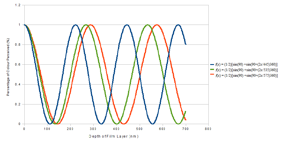
Notice how the graphs start out relatively in sync and become more distorted from each other as the depth progresses to 700nm. This observation will prove integral to understanding why the order of colors seems more wild and the patina deepens.
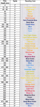
Here is a spreadsheet showing the values represented on the graphs of blue, green, and red light in increments of 10, along with the resulting intensities of white, cyan, magenta, yellow, leftover blue, leftover green, and leftover red lights and the resulting color transmitted back to the viewer. I included these extra columns and values only to show where exactly how I determined my resulting colors. Since his spreadsheet may be overwhelming, I will include a condensed spreadsheet summarizing this information.

Here is the condensed and summarized chart based upon the data displayed above. What I determine a cycle to be is when the colors start repeating. In the data set from 0nm of depth of the patina to 700nm of depth, I can identify three distinct cycles of colors.
 Conclusion:
From the data I calculated and the graph that was produced, I can conclude that the colors present on coins repeat in a cycle of yellow, to orange, to red, to violet, to blue, to cyan, and then to green, which repeats in following cycles, with the colors becoming darker as the patina deepens. The darkening of the colors results from a decrease in the average amount of white light produced in each consecutive cycle, which is caused by the functions of blue, green, and red coming out of sync with each other, as observed on the graph. So, as a result, the colors acquire a darker hue with each consecutive cycle. In effect, I showed that there is most definitely an order and pattern to the toning of high-grade coins. As had stated earlier, here are the coins with numerals for each correct consecutive color in its progression of toning according to my model:

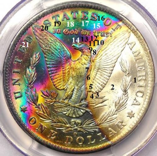
As seen in the pictures, the first coin in question start out with no toning, but that is as far as I got before reaching a toning color that did not fit the natural progression; a dark purple superseding a white, unpatinated surface. Thus, by my model, the toning exhibited by this coin is artificial. The second coin in question followed my model to a tee, although I left out some stages in order to keep the coin from being too cluttered. It starts out white (1), then goes to a light gold (2 - 4), then amber (5), then orange (6), then dark purple-blue (7), then cobalt blue (8), then cyan (9), then pale blue green (10), and so on and so forth until magenta-blue (21. Thus, by my model, the toning exhibited by this coin is natural. The first coin was graded by the Numismatic Guaranty Corporation (NGC) as Uncirculated Details with artificial toning. The second coin was graded by the Professional Coin Grading Service (PCGS) as Mint-State 63 with natural toning. Based on this evidence, I conclude that my model works as designed.
Evaluation: Although I think I was fairly thorough in this exploration in explaining why toning is not just a random process, the assumptions that I stated in the introduction automatically give limitations to this exploration. For example, the angle of incidence is not always 90°; a coin can be tilted and rotated under a single light source, thus making the angle of incidence quite different. I have observed this with a toned coin, with which at certain angles the toning seemed to turn a dull color or disappear altogether. Also, I assumed that the light source produced equal amounts of blue, green, and red light, giving off pure white light. However, most light sources are not "pure;" most have a yellowish or orange tint, signifying that there are unequal amounts of blue, green, and red light. For example, I held a toned coin up to a bluish light and most of the colors seemed to fade away and the blue became more pronounced. That was an interesting phenomenon to observe, and it shows that varying light source purities do have effects on the appearance of toned coins. The other aforementioned assumption that I need to address is that the cone receptors in the human retina respond most strongly to the peak wavelengths of 445nm for blue, 535nm for green, and 575nm for red. I have seen many variations of these values, but no one set of values was made the standard between all sources. Furthermore, it is highly likely that the strengths of the cone receptors depends on the genetic makeup of the human (Wikipedia). Further advancements in all of these assumptions to make a comprehensive field could be done in the future in order to expand this exploration. Such an endeavor would be interesting to see mathematically how the light source, angle of incidence, and variations between cone receptors affect the perception of the color of toning.
My final assumption was that every silver coin that does not follow the previously-stated pattern were victims of being treated with fake toning. As will most things in science, there are exceptions to every rule. This exploration was limited in the respect of identifying and explaining these exceptions. Also my sampling of two coins is far too small to make a conclusion that this method is fail-proof. To get a more accurate idea as to the accuracy of my model, I would have to use a far-larger sample size of coins. All in all, though, this exploration is a strong foundation for identifying a pattern in the order of colors on naturally-toned coins.
Resources:
Information:N.a. "Tertiary Color." Wikipedia. N.p., N.d. Web. 2 Mar. 2014.
http://en.wikipedia.org/wiki/Tertiary_colorN.a. "Cone Cell." Wikipedia. N.p., N.d. Web. 3 Mar. 2014.
http://en.wikipedia.org/wiki/Cone_cellKurz, Doug. "Towards an understanding of the color progression on toned coins." Jhon E. Cash. N.p., 27 Feb. 2009. Web. 4 Feb. 2014.
http://www.jhonecash.com/research/t..._physics.aspN.a. "Is the sum of two sine waves at the same frequency always a sine wave?" EDABoard. N.p., Nov. 2011. Web. 4 Feb. 2014.
http://www.edaboard.com/thread278348.html Russel, Daniel A. "Acoustics and Vibration Animations." acs.psu.edu. Pennsylvania State University, 25 Jul. 1996. Web. 4 Feb. 2014.
http://www.acs.psu.edu/drussell/Dem...osition.htmlN.a. "Interference and Colour Part III - Mathematics of Thin-Film Interference." University of British Columbia - Faculty of Science. University of British Colombia, 24 Jan. 2011. Web. 2 Mar. 2014.
http://c21.phas.ubc.ca/article/inte...interferenceImages:http://www.ebay.com/itm/1878-S-MORG...em2c7c1ba0a3http://www.ebay.com/itm/1884-O-Morg...em20df6f914bhttp://c21.phas.ubc.ca/article/inte...interferencehttp://www.mediacollege.com/audio/0...raction.html